Adjusting Axial Position Probes
Technicians favour two adjustment versions; both of them are described below.
kmo turbo clearly favours version 1.
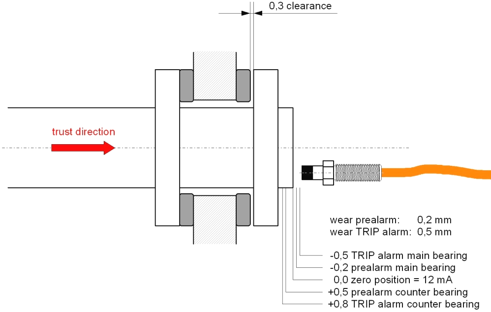
Adjustment Version 1:
The rotor is pushed into its standard operating position, indicated as zero position. Advantage of this adjustment method is a displayed "0" while operating, which makes it easy to recognize each irregularity. Due to the bearing clearance the limits for positive resp. negative deviation have to be adjusted asymmetrically.
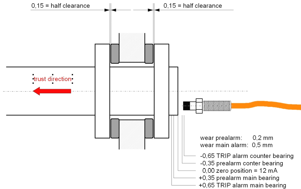
Adjustment Version 2:
The rotor is placed in the middle of the bearing clearance. This is the zero position. To position the rotor a dial gauge has to be installed in a proper location. This adjustment method becomes confusing, if due to the design additionally to the clearance of the axial bearing the clearance of the trust collar of the gear has to be considered. A further disadvantage is that during operation not "0", but in a simple case the half clearance of the bearing is indicated (as shown in the scetch below: + 0,15 mm). For the operator in front of the display it is difficult to recognize irregularities.